Strength of Material
Civil Engineering
Hooke’s Law
- It states that the strain in a solid body is directly proportional to the applied stress and this condition is valid upto the limit of proportionality
Limit of proportionality
- it is the stress at which the stress-strain curve ceases to be a straight line. It is the stress at which extension ceases to be proportional to strain. The proportional limit is important because all subsequent theory involving the behavior of elastic bodies is based on the stress-strain proportionality.
Elastic limit
- it is that point in the stress-strain curve up to which the material remains elastic, i.e. the material regains its shape after the removal of the load.
- However, for many materials, elastic limit and proportional limit are almost numerically the same and the terms are sometimes used synonymously. In case where the elastic limit and proportional limit are different, the elastic limit is always greater than the proportional limit.
For a biaxial state of stress, normal strain along the horizontal X-axis is given by,
εxx=σxE−μσyE
Where, εxx is the normal strain along the horizontal X-axis; σxandσy are the normal stress in the direction of the horizontal X-axis and vertical Y-axis respectively; E is the modulus of elasticity of the material and μ is Poisson’s ratio.
 |
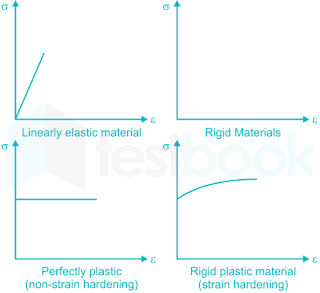
| stress strain diagram for various types of material |
Young's modulus (E)
- Young's modulus is a measure of the ability of a material to withstand changes in length when under lengthwise tension or compression.
- Young's modulus is equal to the longitudinal stress divided by the strain within the elastic limit.
Poisson’s ratio (μμ)
- Poisson's ratio is the ratio of lateral strain to longitudinal strain in the direction of stretching force within the elastic limit.
Bulk modulus (K)
- It is defined as the ratio of the developed stress in the body to the resulting relative decrease of the volume.
Rigidity modulus (G)
- Shear modulus or modulus of rigidity or rigidity modulus is defined as the ratio of shear stress to the shear strain.
When the temperature of a material changes there will be a corresponding change in dimension.
- When a member is free to expand or contract at one of the ends, due to the rise or fall of the temperature, no stress will be induced in the member.
- But, if the material is constrained (i.e. body is not allowed to expand or contract freely), change in length due to rise or fall of temperature is prevented, and stresses are developed in the body which is known as thermal stress.
Stresses in Constrained material:
- When the temperature of the bar is raised, and the bar is not free to expand, the bar tries to expand and exerts axial pressure on the wall. At the same time wall puts equal and opposite pressure on the bar which will develop compressive stress in the bar.
- If there is a drop in the temperature of the bar, the bar will try to contract, exerting a pull on the wall. At the same time, the wall offers equal and opposite reactions exerting a pull on the bar which will develop tensile stress in the bar.
- Increase in temperature → Compressive stress
- Decrease in temperature → Tensile stress
Modulus of resilience
It is defined as proof resilience per unit volume. It is the area under stress-strain curve up to the elastic limit.
Proof resilience
It is defined as the maximum energy that can be absorbed within the elastic limit, without creating a permanent distortion.
Modulus of toughness
It is ability of unit volume of material to absorb energy up to fracture. From the stress – strain diagram, the area under the complete curve gives the measure of modules of toughness.
Assumptions in the theory of bending:
- 1. The radius of curvature is very large compared with the dimensions of the cross-section.
- 2. The beam is made of homogeneous and isometric material and the beam has a longitudinal plane of symmetry.
- 3. The resultant of the applied loads lies in the plane of symmetry.
- 4. The geometry of the overall member is such that bending not buckling is the primary cause of failure.
- 5. Elastic limit is nowhere exceeded and ‘E' is the same in tension and compression.
- 6. The transverse sections which were plane before bending, remain plane after bending.
- 7. The beam is initially straight and has a constant cross-section.
Slenderness ratio
- (λ) = Leff/r
- Where,
- Leff = Effective length for the column, and r = minimum radius of gyration.
- Various column conditions and effective length are tabulated below.
.
Condition (distance between supports is ℓ) | Effective length |
Both ends Hinged (pinned) | L |
One end hinged, another fixed | L/√2 |
Both ends fixed | L/2 |
One end fixed and other end is free | 2L
|
Struts:
- These are long and slender structural members in an assembly that are subjected only to an axial compressive force.
- They predominantly fail by buckling but sometimes the yielding failure occurs in compression before buckling.
- These members are structurally analogous to columns. So, the buckling strength of struts is similar to that of the colum
Shear Stresses:
Due to the shear forces the beam will be subjected to shear stresses. These shear stresses will be acting across transverse sections of the beam. These transverse shear stresses will produce complimentary horizontal shear stresses, which will be acting on longitudinal layers of the beam.
τx=VAY¯Ibx
Where,
V = Shear force (Due to change in bending moment)
A = Area above or below the section in the cross-section
Y̅ = Distance from centroid of area from neutral axis
I = Moment of inertia of total cross-section about neutral axis
bx = Width at the section
Nominal or average shear stress (τavg):
τavg=ShearforceCross−sectionarea
The relation between maximum shear stress (τmax) and average shear stress (τavg) for different shapes is given in the below table
Section | τmax/τavg | ΤN.A/τavg |
Rectangular or square | 3/2 | 3/2 |
Circular | 4/3 | 4/3 |
Triangle | 3/2 | 4/3 |
Diamond | 9/8 | 1
|


